Okay, some progress on the battery front.
I seem to have successfully made my own NiMH replacement pack using an Alkaline holder.
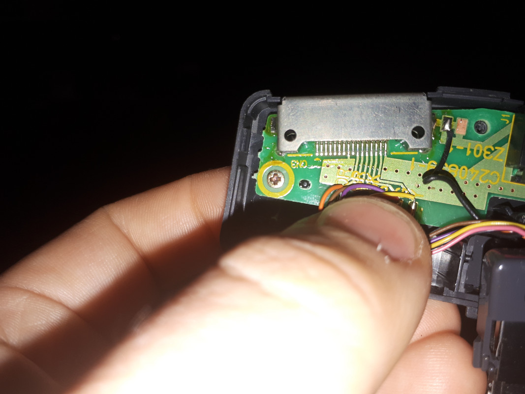
Deconstructing the OEM battery pack told me the following:
Negative terminals are shorted together, positive terminal, only the small one is apparently connected to the battery proper.
So then, why not use 2 NiMH AA cells and make my own janky contacts?
Behold the majesty
(note that it is very easy to remove the original contacts without destroying them. Use a fine flathead screwdriver and wedge it under each side of the little flaps on top of the contact
):
Positive side:
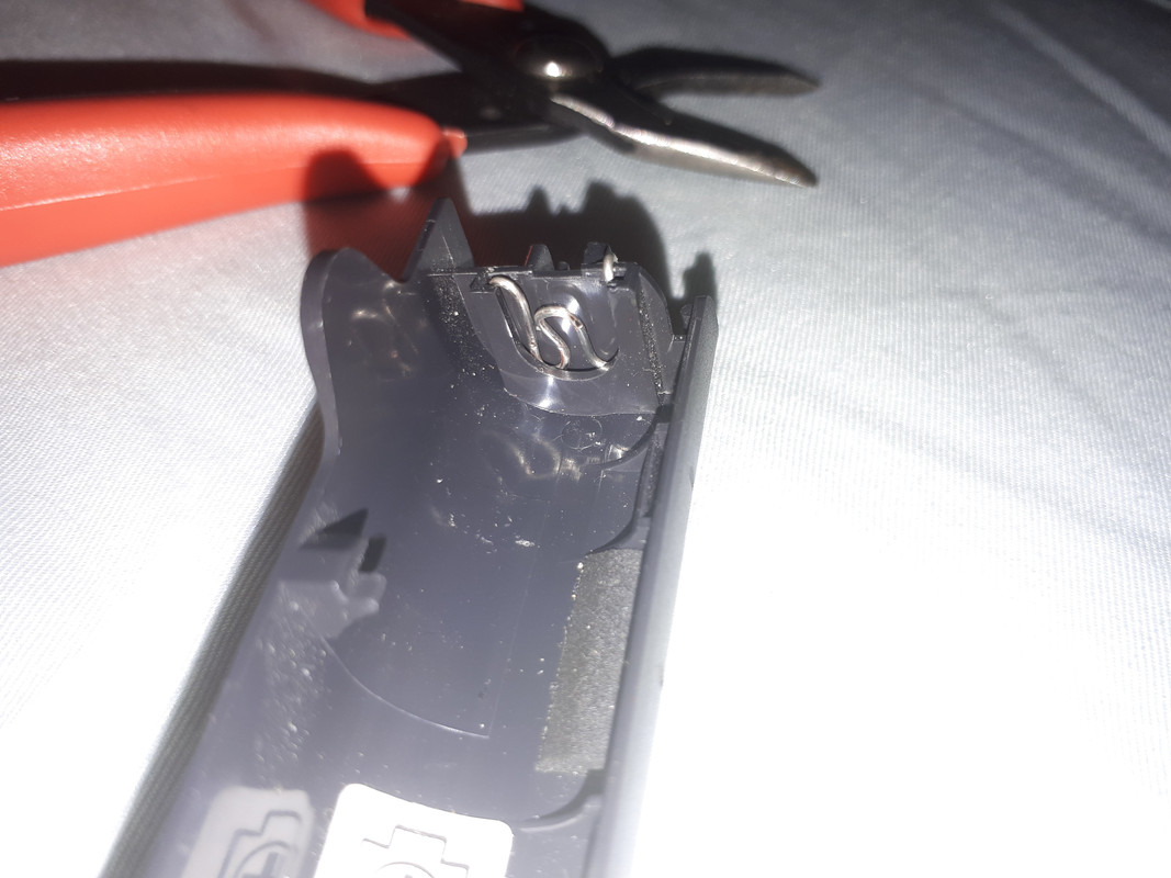

Negative side:


I used stripped solid core wire to make the contacts, and subsequently wrapped the outside with aluminum foil. It was a tight squeeze fitting it in the battery bay, but my charger LED is on!
I put really crummy old flat NiMH batts in there for now, hit or miss if they will actually work when all is said and done. But I have some new amazon basics batteries lying around somewhere...
I also noted something interesting. The charger brick and the power brick are separate; the power brick can plug into either the port replicator
(not the dock
) or the charger brick and it supplies +5V. The Charger brick has printed on it that it has a 5V power input and a 3.7V power output. So it looks like the NiMH charging circuitry is contained inside the charger brick. That explains why there is an extra wire on the "Charger" side of the port replicator
(see pictures above
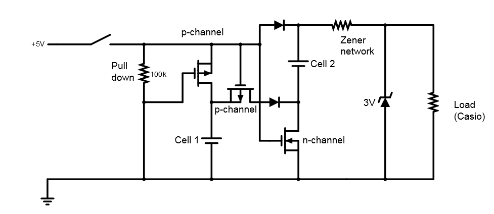
). I will hopefully trace out all the pins before I go to sleep tonight. This potentially makes things a little more difficult trying to make an effective drop-in lithium battery. If I can find an always-5V-point inside the charge circuitry then I have designed a simple circuit that would allow for charging of the lithium ion AAs I was talking about earlier. The rough sketch of the charge circuit for the lithium ion AA batteries is below.
 Edited by astrosynthesist 2020-01-14 5:37 AM