Disassembly Guide for the hp 620LX
CESD|200196Applies To
- Handheld PC 2.0
- Handheld PC 3.0 Professional
Overview
This CESD details the chassis disassembly procedure for the Hewlett Packard 620LX Handheld PC.
More Info
The following steps outline how to disassemble the screen and chassis for the 620LX for maintenance purposes.
WARNING: Disassembling and electrical device is inherently dangerous both to you and the functionality of the device. HPC:Factor accepts no liability for loss or damage caused as a result of following the steps outlined within this article. Always ensure you follow standard electrical safety guidelines and if in doubt seek professional advice.
Before you begin
Before you proceed with the disassembly instructions you should ensure:
- You have made adequate backups of your device data
- Remove any PC Card, CF Card or connectivity peripherals
- Remove the Coin Cell backup battery
- Remove the AC and main battery pack
Disassembling the Screen
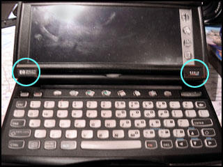
- Rotate the PDA and open the screen so that the device sits in a typing position.
- Lift the glued on logos (Hewlett-Packard [left] and HP 620LX [right]) and release the screws beneath them. Do not apply too much force to any of the the mouldings as any load now rests upon the clasps.
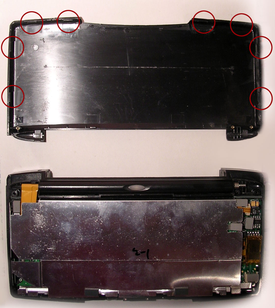
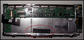
- Carefully close the PDA. In the graphic (click to enlarge) you can see the position of the plastic pins which hold the display backside. Release them using your finger nail - do not attempt to use any form of tool or leverage mechanism. Damaging these clips will render the display unable to return to a sealed state.
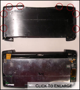
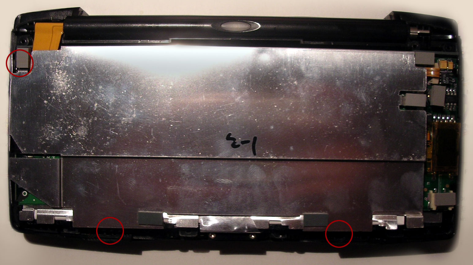
- Take off the back of the display revealing the aluminium back plate as shown in the phorograph.
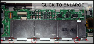
- Take off the aluminium back plate. Clip positions have been highlighted on the photo below.
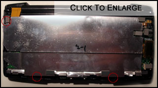
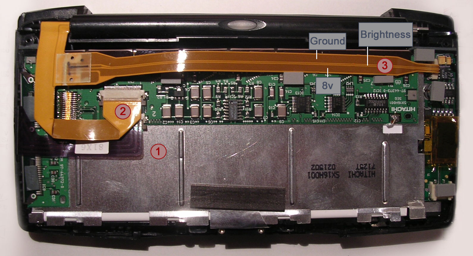
- You can now see three cables. Release them and take the display component out of the PDA.
- The purple cable is the data line for the touch screen.
- The broadest cable is the display source.
- The third one going off to the left is the cable for the power source for the display.
- The touch screen itself is held in the case by a tactile adhesive pad. Release it carefully ensuring that the touch screen doesn't slip.
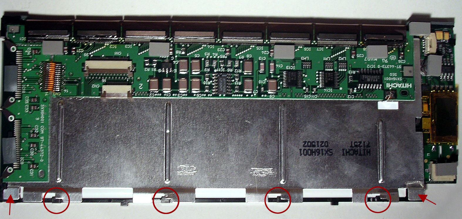
- The white tube with the 2 wide, insulated cables coming (not shown) out stores the CCFL (Back light) tube. If you are an electrician you can conceivably replace the tube with a more efficient version, or with LED lamps which fit the diameter of approximately 2mm. To release the CCFL:
- Carefully bend out the aluminium holders (marked in photo) so they don't arrest the tube any longer.
- Take the tube carefully out in its gray protectors by a matter of only a few millimetres so you can access the end of the shorter cable.
- Sever the cable and pull carefully (!) out the tube
Note: CCFL's are fragile, glass objects and liable to fracture. If you intend to reuse the tube, you should not touch the glass region on the tube as oils from the skin can degrade the lamp.
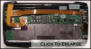
Display Back light Power cable
Looking at the power cable from the front in its housed position on the CCFL:
- The upper pin of the power cable is GND
- The middle is the brightness control
- The lower one +8.27 V approximately (the documented schematic voltage is unknown and may be able to serve 12v)
Acknowledgements
With thanks to Marco Schuster for working with us on this article