Rebuilding / Re-celling a dead Battery How-to GuideCESD|200224Applies To
OverviewThis article discusses the physical and electrical steps required to rebuild / re-cell a Handheld PC battery pack. More InfoWARNING: The steps outlined in this article are potentially VERY DANGEROUS. They should not be attempted by inexperienced users.
Lithium battery packs are potentially explosive when exposed to heat or shock. If you follow this guide you must read it in full before attempting to under take any work and you do so at your own risk. Do you have a dead battery and need to rebuild it because you cannot find one for sale anywhere? Well then it is time to get started and quit putting it off. For this tutorial, I am going to rebuild the battery pack for my NEC Mobilepro 880. But you could apply the same principals to nearly any HPC battery. The tools I will need to perform this task are:
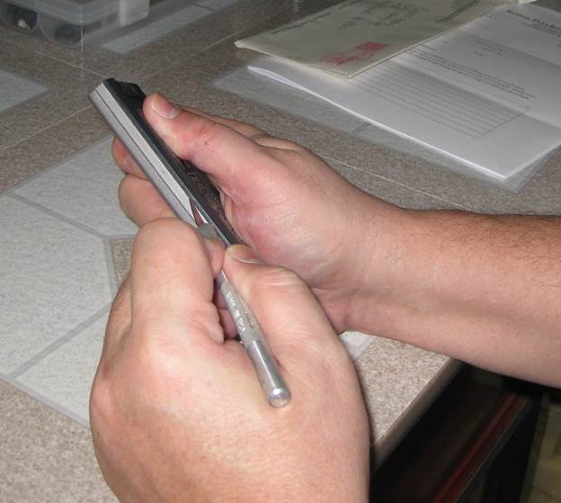
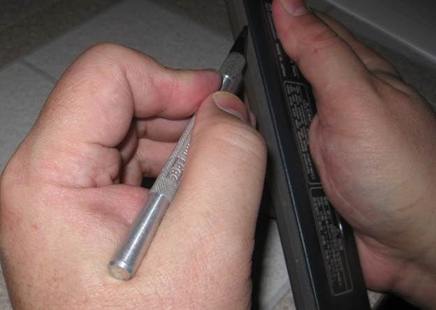
Before we continue, ask yourself, how can you tell your battery is bad? The answer to that question is not as simple as you would think. There are many reasons why your portable device is no longer portable. Luckily, almost all the time it is the battery that is bad. But be aware, it may not be a battery problem itself. There may be a fault in the devices internal charging circuit that prevents the battery from being charged. The only way to be sure is to try another battery that you know is good in the device and see if it charges properly after being exhausted. Sometimes it is as simple as a loose battery connection inside the device and in this case it is a physical problem, not an electrical one with the charging circuitry or the battery itself. Most devices have a red led lamp that lights up when a low battery is in place, alerting the user that the battery needs to be charged. Plugging in the charger, the battery will charge to a point where it is full, and the led will turn from red to green. Most bad batteries will go from red to green in a matter of minutes, normally less than 10 minutes. The good news in this case is that the devices sensing circuitry is working fine. It believes the battery is good. The bad news is that it is not. This circuitry differs on different devices and batteries. Some actually measure a reverse bias voltage to tell when the battery is charged. A more common method is a termistor. This is a small electronic component that heats up when electricity passes through it. When it gets warm enough, then the termistor “opens” the electronic circuit, preventing further voltage from entering the battery, thus preventing it from overcharging. The key point here is that most battery packs have 2 or 3 or more cells in them. Most termistor circuits connect the individual cells in a electronic parallel fashion. This means that as soon as one battery is fully charged, then the charging stops for all batteries. In this case, the weakest battery is the link in the controlling factor. So you may have a battery pack that doesn’t charge any longer, but it is only one of the cells that is bad, not all of them. So what do you do? Replace all the cells or just the faulty one? To determine the faulty one, you would have to attempt to manually charge each cell individually until you found which was bad. And after replacing it, might wonder how long the others will last now that the pack has been repaired. If you are like me, you won’t mess around doing this. I prefer to change all the cells at the same time, because let’s face it...the battery rebulding is an effort and time consuming. But when you are done...it is extremely rewarding to see your device work like it should again. One more thing I would like to say about the individual cells. You can always replace the existing cells with one of a larger capacity, but never do the inverse. Using a 2600mAh battery is fine when replacing an 1800mAh battery. But not the other way around. Most of our HPCs are dumb devices when it comes to battery charging. That is they supply a constant voltage to a battery pack, and rely upon the circuitry of the battery to cut off the charge when complete. This means that by using higher capacity batteries, you can get extended usage from a battery beyond the original design. This can have a minor drawback as well. Some HPCs are calibrated to a specific voltage as designed by the battery. This means you can get erraneous readings on the battery capacity when checking the battery using the software in the control panel. A minor problem as it doesn’t affect usage of the device at all...just reports erraneously. Some CE devices actually have embedded software that allows you to calibrate the battery charging so that it actually coincides with actual physical characteristics of the main battery. Enough talk... let’s rebuild this battery. Step 1The most difficult of any battery rebuild is taking apart the old battery pack. This has to be done very carefully and very slowly. Inside the battery pack is sensitive electronic circuity. This circuity varies from device to device and newer devices have much more circuity than older vintage handhelds. The circuity normally lies inside the case right next to the connector, but may extend the length of the battery pack, so you have to be careful during this entire process. The case of the battery is normally secured with one of two methods. The first is that the case has been glued using a super strong epoxy or adhesive that actually melts and chemically bonds the case halves together. The other method uses ultrasonic waves to weld the case halves together. Either method works well and makes it very difficult for the user to pull the battery apart without serious effort. To open the battery up, the best method is to score (cut) along the seam lines of the battery where it has been assembled. On my Mobilepro battery that seam is easy to see because one part of the case is silver and the other half is dark gray. YOU NEED TO BE PATIENT AND TAKE YOUR TIME...AND BE VERY CAREFUL THAT YOU DON’T CUT YOUR FINGERS OFF. DO NOT FORCE THE CUTS, TAKE YOUR TIME!
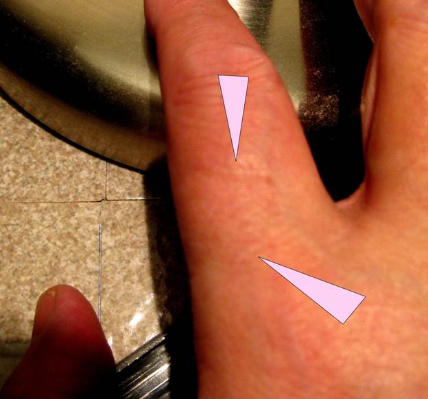
Can you see in the above picture how one simple slip and I’ve slashed my right hand with the Xacto knife?
The truth is that I don’t press hard at all, just firm and steady, and I never force the cut. I’ve done this so many times that I know enough not to get careless or rush. I still have scars on my right index finger where I had to learn this lesson the hard way.
It took me about 200 scores along each seam to finally cut through the plastic case, but when I did...it came apart very easily.
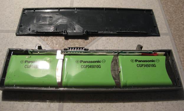
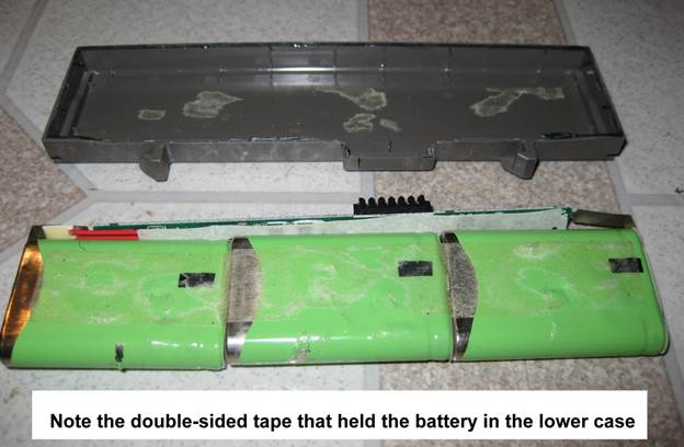
This is where I would normally tell you to take a picture. A picture is worth 1000 words when it comes to reassembling everything and making sure that you end up with something similar to what you started with. In the picture above, the case half is off and you can see the 3 Panasonic cells sitting inside. Most important, not the direction of the cells, especially the polarity. The positive end of the battery is facing to the left and you can see the motherboard connector is more to the left of center in the picture. You sure don’t want to mix up the batteries and have the negative side facing left when you resolder them. Now it is time to take them out of the lower case shell.
Step 2They sure didn’t just fall out. I had to pry them out with a flat tip screwdriver. This is because they were taped in place with very strong tape. Some battery packs I’ve taken apart have the cells actually epoxied into position or glued with some type of adhesive. Now it is time to separate the batteries from the circuit board.
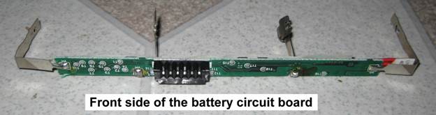
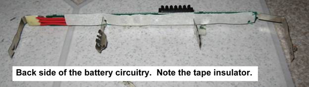
Step 3Most all batteries you will take apart have the cells connected mechanically. That is the wires or contacts are not soldered into place. They actually have a mechanical punch that pressure fits the contact strip to the battery securely. THIS IS BECAUSE LITHIUM ION BATTERIES CAN EXPLODE WHEN EXPOSED TO EXCESSIVE HEAT! With that said, I use low-temperature solder when I reconnect batteries. Rosin core is an excellent choice for electronics and does not have the potential to damage electronic components that acid core solders do. While normal solder melts at about 375F (190C), low-temperature solder melts at about 270F (130C) and makes soldering much easier and safer when working with battery cells. Wedging a knife tip under the metal strips on battery, I was able to separate the cells as you can see above, and this left me with just the circuitry.
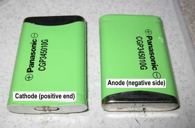
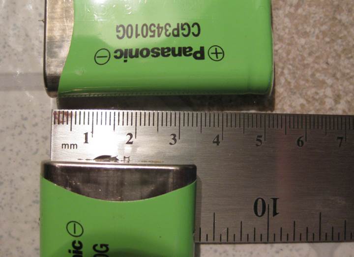
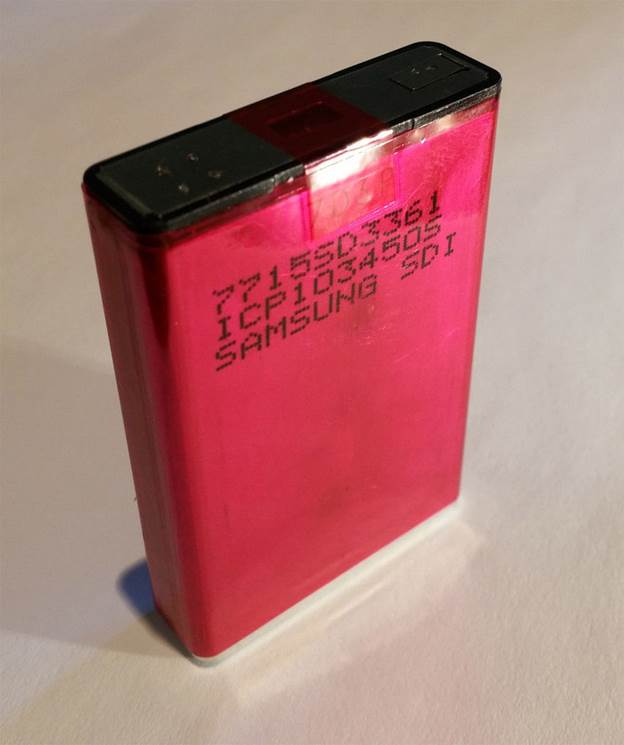
Step 4Now all I have to do is find some replacement batteries. Most of the major battery manufacturers label their batteries in accordance with their sizes. For instance, the cells in a Mobilepro 900 are 18650 cells. This means they are 18mm in diameter and 650mm long. This holds true for these prismatic cells as well. I performed an eBay search for the Panasonic cells, but none came up. But what did come up was a cell that is physically and nearly electronically identical. Although these are made by Samsung. So I ordered 3 of them at a cost of $6 each.
Here you can see that they are 34mm wide and 50mm long. They are also 10mm thick.
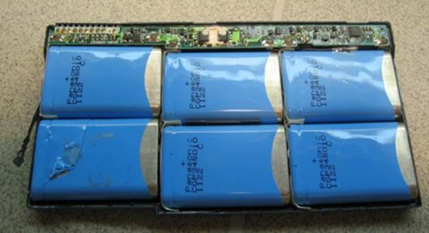
If I had a compatible old laptop battery, I could have salvaged the cells from it. The Fujitsu Lifebook S-Series battery, part FPCBP25 actually contains 6 of the Panasonic cells.
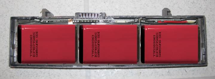
Step 5Well, I started this tutorial a few days ago. The Samsung cells arrived in the mail today. They have a small charge in them and I soldered the to my circuit board and placed it back in the lower case half. By the way, if you don’t like solder wire, solder paste works well too! And it is easier to apply. Just brush it on and heat it up.
Step 6Now to test it...glue the cover back on and plug it into the Mobilepro and let it charge. BTW, I prefer to use epoxy glue and just fill the seam and let it dry. I hold the halves tightly together with rubber bands during this process. I like the epoxy because after drying you can sand it down and touch up the battery with paint if you need to.
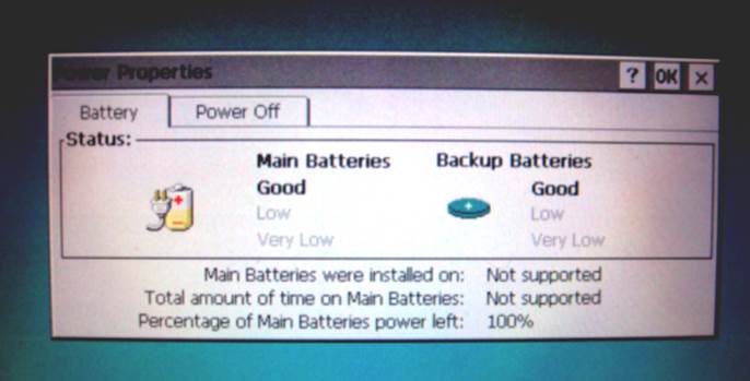
The original cells were rated at 1400mAh. The new cells are 2000mAh. The battery charged up overnight, and I turned on the MP880 this morning. After letting it loop an MP3 song for over a half hour I was still showing 100% charge. I continued to let it run and after 5 hours I’m still going strong, though I am now down to 50% charge. Still, it appears my battery rebuild was successful! Final thoughts to remember:
REMEMBER, YOU PERFORM THIS OPERATION AT YOUR OWN RISK. AcknowledgementsWith thanks to Rich Hawley for writing this article and exploring the electrical engineering steps required to implement the modification. |